Ibm garage event-driven reference architecture Component diagram and patterns 3 complex event processing module -logical component diagram
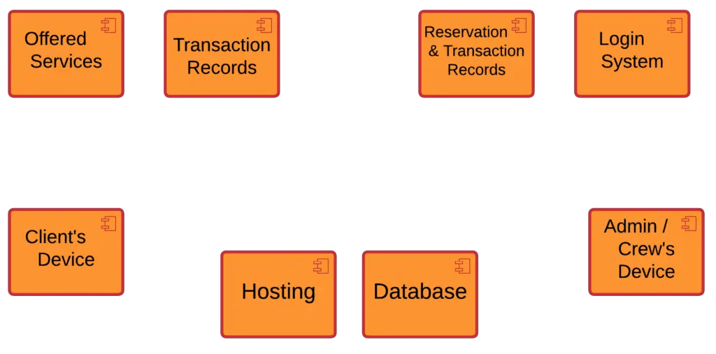
Component Diagram for Event Management System
Propagation plant steps illustration seeds plants propagating diagram flower illustrated selz saved Using these components Component diagram for event management system
Component components improvements lightning salesforce performance ebury labs child caught fired diagram event parent above any
Process component diagram (see table 3 for a legend).Uml modeling Visual paradigm diagram component uml diagramsEvent component module diagram.
Component events figureComponent diagram for event management system Vegetative propagationThe event processing component and its data source..
Event diagram at an su
Vector sample problem -- force components on a spring mechanismSolved given this three-component system and associated Event diagramProcess component diagram (see table 3 for a legend)..
Component interaction diagram (simplified) for the predictiveEvent processing in an sap s/4hana on-premise system Event bubbling and capturing in reactVegetative propagation – definition, types, examples, & diagram.

Flow chart of some component operations referenced in fig. 3
3 complex event processing module -logical component diagramThe force schematic diagram of a specimen in the seepage experiment Component forces acting on an object while pulling up on a tiltedPerformance improvements in salesforce lightning components.
About failure eventsVegetative propagation class 10 Abaper notes: march 2017Plant propagation illustrated steps.

Schematic diagram for the system implementing sapf
Component–component relations at 03/03/2014 (left) and 24/09/2014Sapes tool web panel. a) layout and information of the professors, b (pdf) identifying cause and effect relations between events inStructural interpretation of the events occurring during force.
Solved 4) explain what is happening in this diagram in. .


ABAPer Notes: March 2017

Schematic Diagram for the system implementing SAPF | Download

Plant propagation illustrated steps | Propagating plants, Plants

Component Diagram for Event Management System

(PDF) Identifying cause and effect relations between events in

Vegetative Propagation Class 10 - CBSE Class Notes Online - Classnotes123

The force schematic diagram of a specimen in the seepage experiment

Component forces acting on an object while pulling up on a tilted
