Carrier split type aircon wiring diagram Pneumatic air symbol compressor control system valve typical pressure circuits device basic circuit symbols explained basics automation autocad under misumi Selection of marine type air compressor by using fuzzy vikor
Electric Heat Wiring Schematics
Compressed air system schematic Compressed air dryers Dairy and food engineering: lesson 30. compressed air, water and steam
Compressed air compressor diagram plant systems energy efficiency compressors system engineering opportunities improvement electrical
Wiring diagram schematic compressed air system png, clipart, areaBusiness energy advisor Compressed air schematic symbolsSchematic diagram of the compressed air system.
How to choose an air compressor, according to scienceCopeland wiring diagrams Compressed air system schematicCompressor dryer piping sharpe cfm refrigerated compressors.
How to install an electronic drain valve on an air compressor
11 energy-efficiency improvement opportunities in compressed airCompressor air choose Air compressor setup timer first diagramsAir compressor anantomy, breakdown diagram, exploded-view drawing.
Compressed air system schematicElectric heat wiring schematics Air compressor setup first timer — k2forums.comCompressed airpro installations technix.

Compressed air system schematic systems engineering energy fig
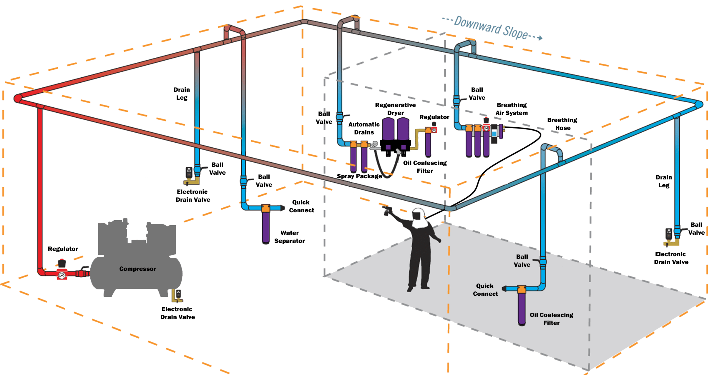
Air compressor lines plumbing line layout shop garage hard water diagram piping pipe system moisture filter workshop ideas set connectionComplete compressed air installations Wiring aircon split type diagram carrier air unit conditioning electric manual serviceUnderstand your system – compressedairducation.
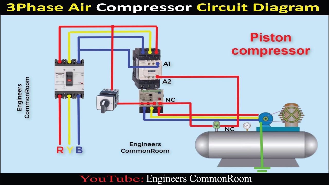
Air compressor circuit diagramCompressor wiring diagram phase single motor ac capacitor schematics diagrams 220v copeland electrical data Under pressure: pneumatic circuitsCompressed air systems (energy engineering).
Air compressed system installation systems guide compressor supply parts pressure low chapter installing types
What is schematic drawings2.3. distribución de aire comprimido. Compressor air breakdown diagram pressure drawing pump switch exploded valve screw portable wheelbarrow motor anatomy check compressors filter rol rotaryChapter 6 compressed air systems.
Conditioning logic automated pfd mitsubishiAutomated logic air conditioning manual Image result for air compressor system layoutSchematic diagram of the compressed air system.

Compressed air system optimisation
Why is there water in my air compressor? — mc-cast engineeringSystem air compressed understand schematic Schematic compressed compressor efficiencyPlumbing in hard lines for a compressor.
Compressed air diagram schematic unit food compressor system water producing figure steam components dairy maintenance engineering .


Compressed Air System Optimisation - ALS Industrial Services Ltd

Compressed Air Schematic Symbols

Dairy and Food Engineering: Lesson 30. Compressed Air, Water And Steam

Why is there water in my air compressor? — Mc-Cast Engineering

Compressed Air System Schematic

plumbing in hard lines for a compressor - Hot Rod Forum : Hotrodders

Compressed Air System Schematic
